
LinkSwitch-TN2 (LNK3205) Noise on input causes heavy ringing on output
Hi,
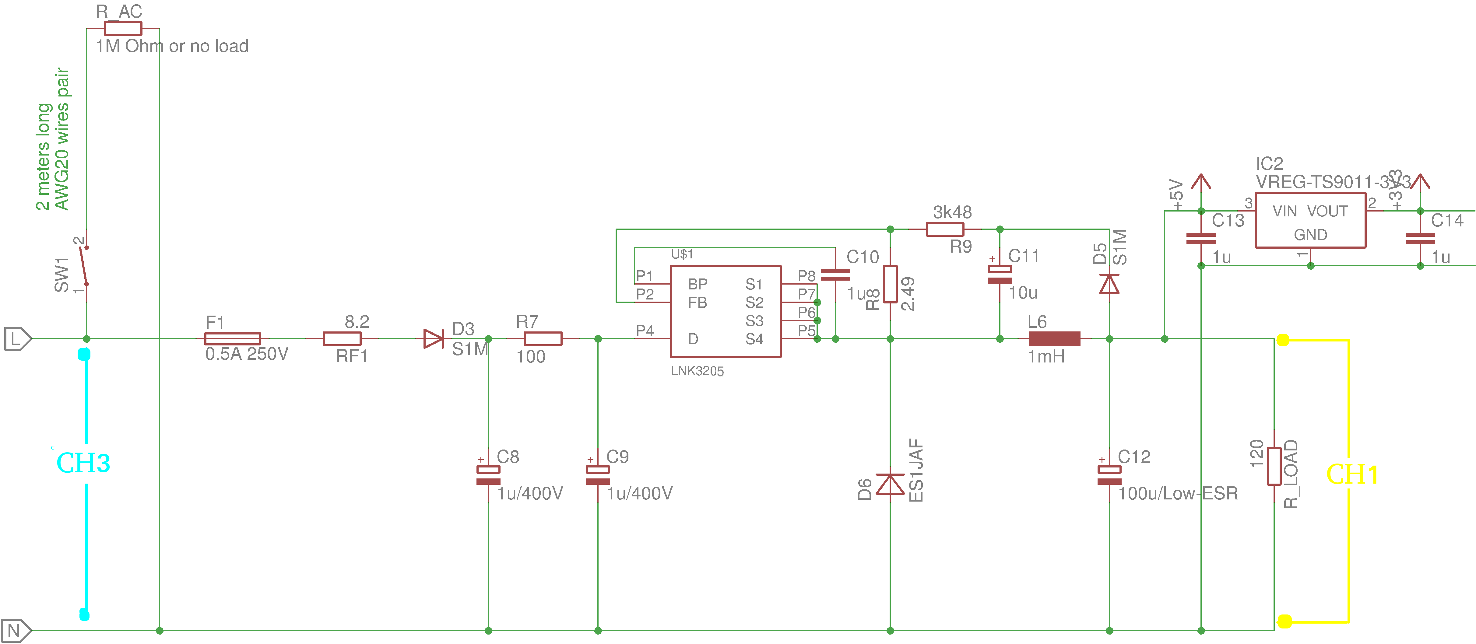
I've built a prototype PSU based on LNK3205 in High-Side Buck Direct Feedback topology. The requirements are to output up to 120mA peak, 40mA continous at 4-5V. In my design the output when loaded is 4.66V which is perfectly ok as it is going to power 5V relay and MCU via 3.3V linear regulator. I power the PSU with 250V AC via separation transformer.
The problem is that I observe catastrophic ringing on the output which gets the output voltage briefly far below 2V when I attach to the input a load or even a piece of floating wire with no load attached (no difference observed). The output voltage drop causes the MCU reset. The wire is attached via mechanical switch. Switching it on triggers problem. Switching it off seems to be ok. Besides this scenario I do get stable output 4.66V with c.a. 0.1V ripple as expected.
I used following components in my design:
Inductor L6: Bourns RL875S-102K-RC (http://www.bourns.com/docs/Product-Datasheets/RL875S_series.pdf) 1mH 2.72Ohm 230mA
FW Diode D6: ES1JAF (http://www.onsemi.com/pub/Collateral/ES1JAF-D.PDF) 600V 35ns.
I attach a schematic of the PSU with indication where is located the switch that causes a problem (SW1). The schematics also indicates where are the scope CH1 and CH3 probes connected.
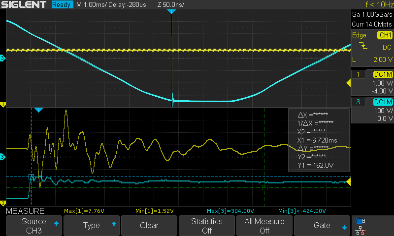
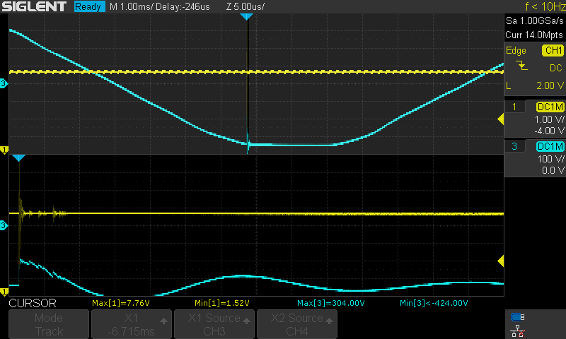
I also attach screenshots from the scope. The image is split. At the top you'll see part of 50Hz AC input, at the bottom you'll see zommed in picture at the point where the switch was engaged and ringing occurred. I tried adding some capacitance at PSU input which has reduced input noise but output hasn't changed much.
Do you guys have any clue what can be the cause and how can I fix that problem?
Files
| Attachment | Size |
|---|---|
| Schematic of the PSU | 92.67 KB |
| Scope screen of input noise and output ringing | 22.64 KB |
| Scope screen of input noise and output ringing zoomed out | 22.01 KB |
| Scope screen of reduced input noise and output ringing with 44nF at input | 20.54 KB |
Comments
Hi Jedidiah,
Yes, R7 was 100ohm resistor when I was writing my first post. I thought that the inductor might help so I've replaced the resistor with 1mH inductor (WURTH 744772102 https://katalog.we-online.de/pbs/datasheet/744772102.pdf) but it didn't really help. Measurements uploaded in this post are with a 1mH instead of 100ohm.
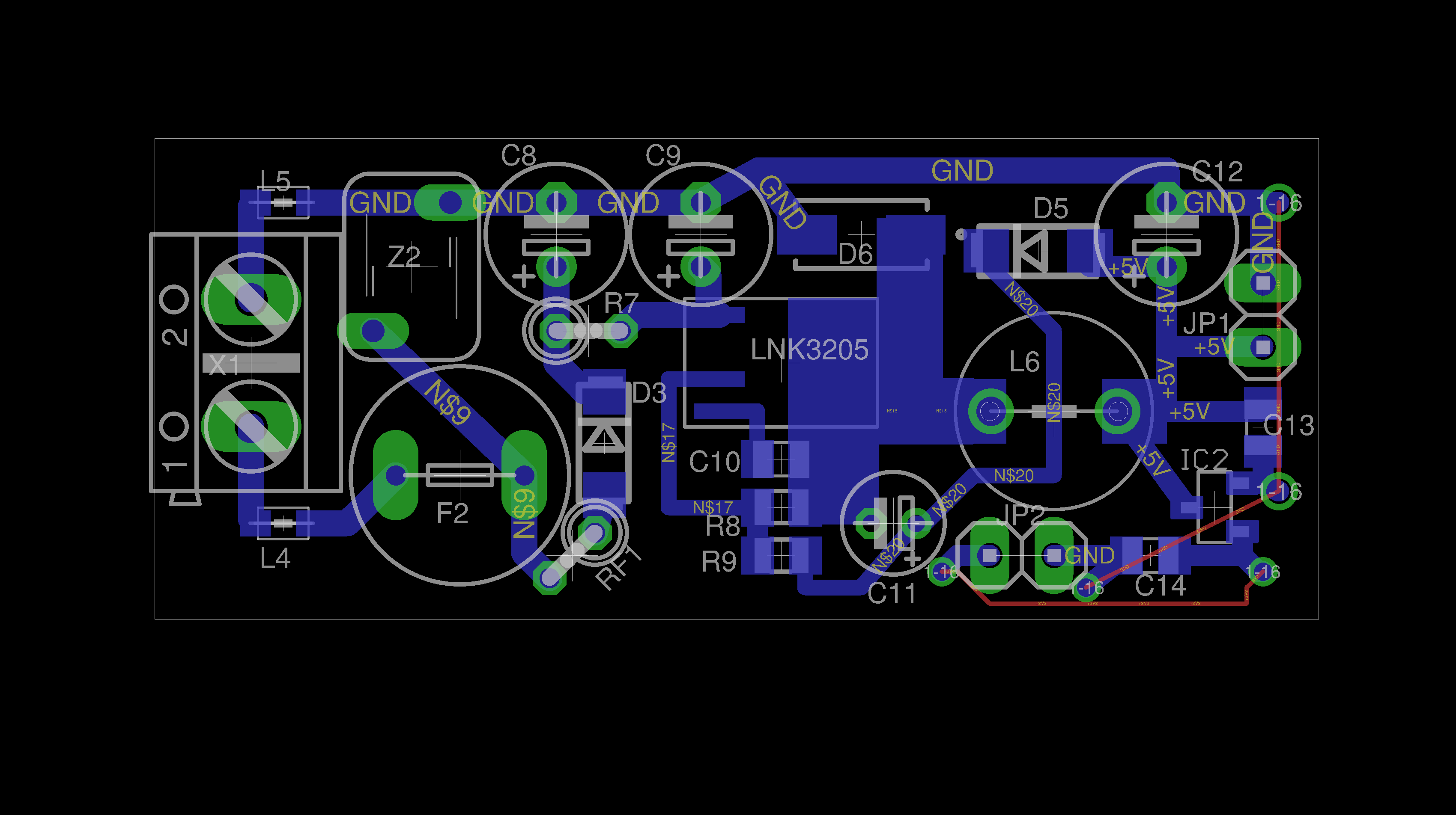
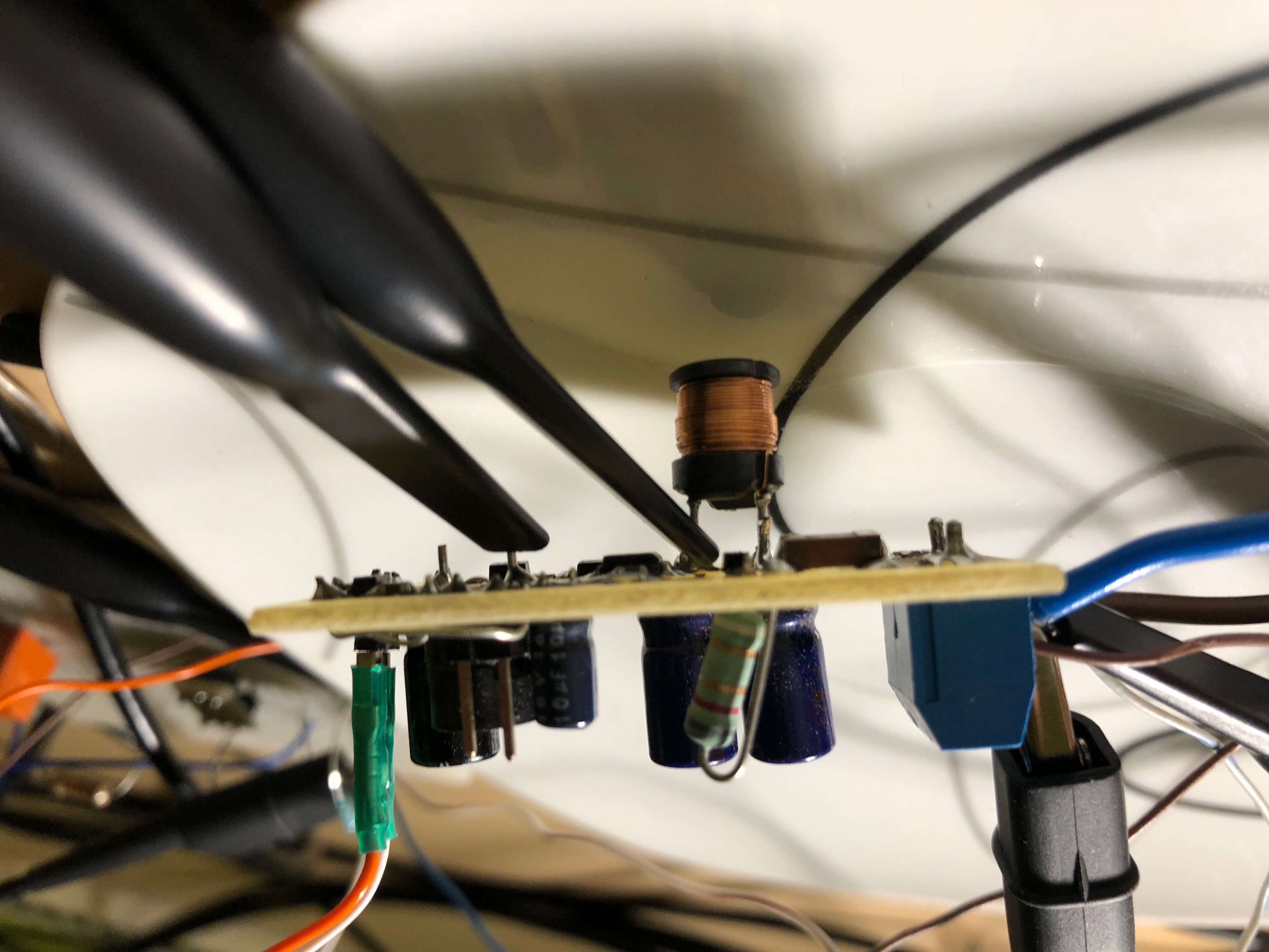
I'm attaching a PCB layout. It is a single side PCB with trace on a bottom (blue) and THT elements on a top. Red is air wires at top side. Please note that the ferrite beads L4 and L5 are not mounted (shorted) and Varistor Z1 is not mounted. The input filter inductor was soldered at the bottom side instead of 100ohm resistor (see picture).
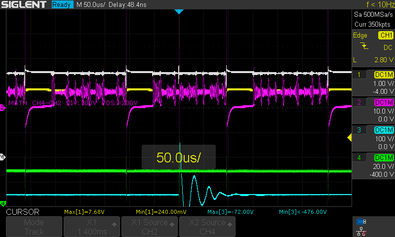
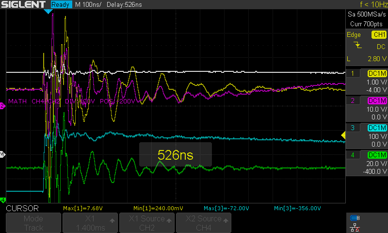
I'm attaching measurements made at input (ch 1, yellow), D6 (ch 2, pink), output (ch 3, blue) and C9 (ch 4, green) at the time when the problem occurs (switch at input gets shorted). I don't have a differential probe so couldn't measure Vds but I include it as math operation CH2-CH4. I'm attaching three pictures at different zoom level.
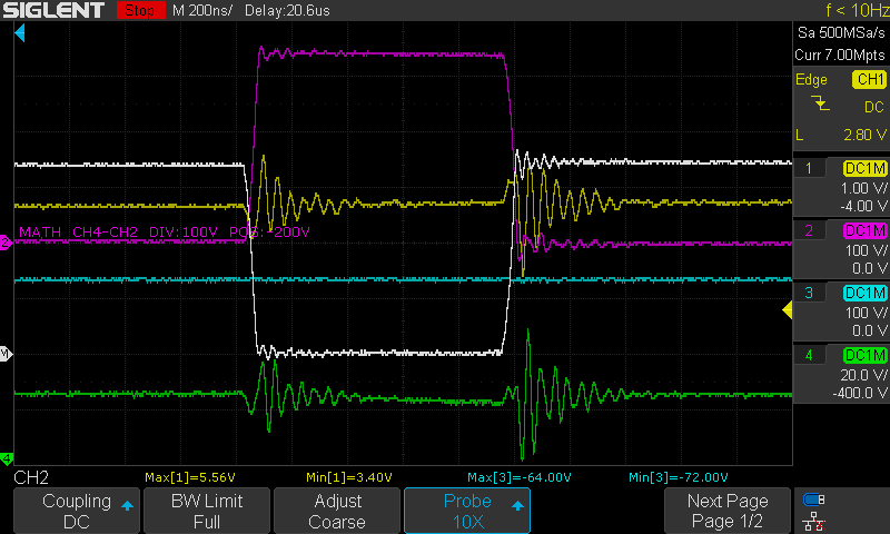
In addition I attach a measurement of regular switching period when everything seems to be ok. You can see the output ringing quite a lot too there.
Best regards.
| Attachment | Size |
|---|---|
| pcb layout | 114.76 KB |
| pcb side view | 1.65 MB |
| scope 1ms/div | 54.51 KB |
| scope 50us/div | 39.12 KB |
| scope 100ns/div | 22.34 KB |
| scope regular switching on/off period | 19.6 KB |
Hi wsowa,
Can you try adding RC circuit across D6? Let's start with 100ohms and 1nF. Add this RC in parallel with D6 diode. Next is let's try placing D5 near C11 is this will reduce the ringing.
Regards,
Jedidiah
Hi Jedidiah,
Thanks for the response. I was thinking that perhaps I made a mistake in the calculations so decided to build the PSU again according to your reference design for 12V (RDR-506), despite my design being 5V, to see if I can see the problem there too and indeed I can still observe it. See the schematics, PCB and scope measurements attached (IS_RDR-506.png). The PCB is a single side PCB with THT components on the top side and SMD components on the bottom. I've removed and shorted diode D2 comparing to reference design since I've been shorting it with the scope probe GND anyway.
Please note that in my previous post I've attached scope screenshots indicating heavy ringing across the flywheel diode which seem to be due to incorrect measurement procedure. I've been measuring it without short group loop on the probe (probe grounded via other's channel GND). Measuring with short ground on channel 2 reduced the noise significantly. Moreover it showed that when the problem occurs (i.e. when I short the switch and I see output ringing), there's no noise across the diode so I didn't really expected the RC snubber across the diode to help...
So I've added the RC snubber as you've proposed across the flywheel diode however it didn't help at all. The circuit runs quite hot now (c.a. 80 deg C) thought. See attached measurements and schematics/PCB with the snubber added (IS_RDR-506snubber.png).
I decided to take a step back and start measuring input for the circuit stage by stage in isolation.
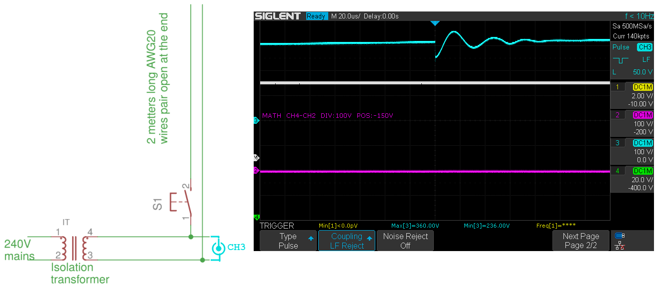
First I've checked what happens when I just short the switch with no PSU connected. See measurements and schematic attached: IS.png
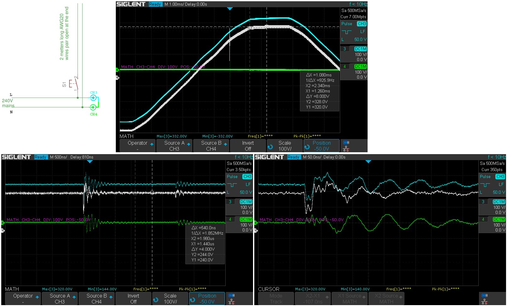
I was surprised with the low freq noise. I also do see it when measuring complete circuit. I suspected it was caused by the Isolation Transformer's inductance. I tried the same with direct mains input (MAINS.png) and there was no low-freq noise.
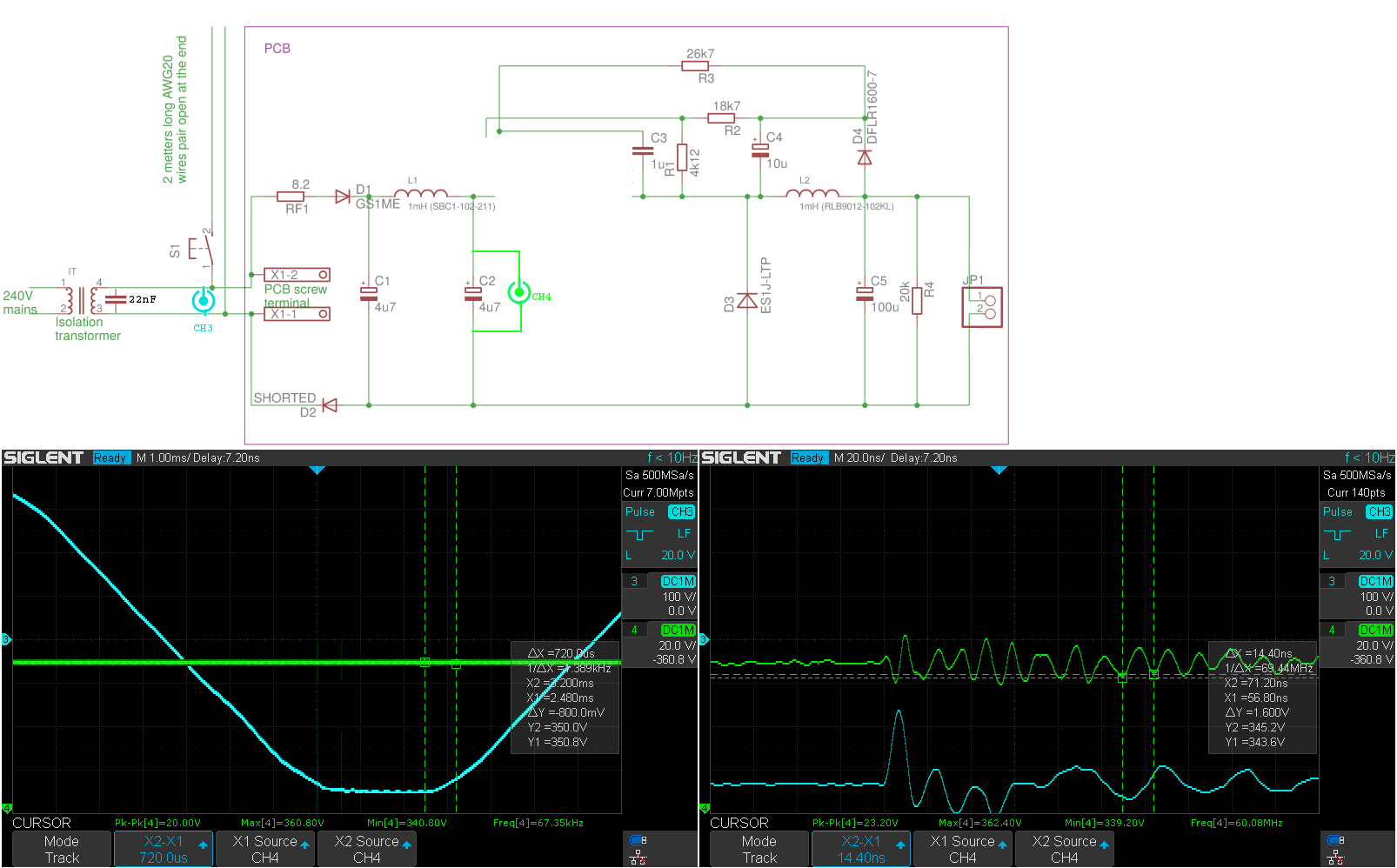
Then I've added 22nF to the Isolation Transformer's output and that's eliminated the low-freq ringing from the setup with Isolation Transformer (IS22nF-direct.png). So far so good.
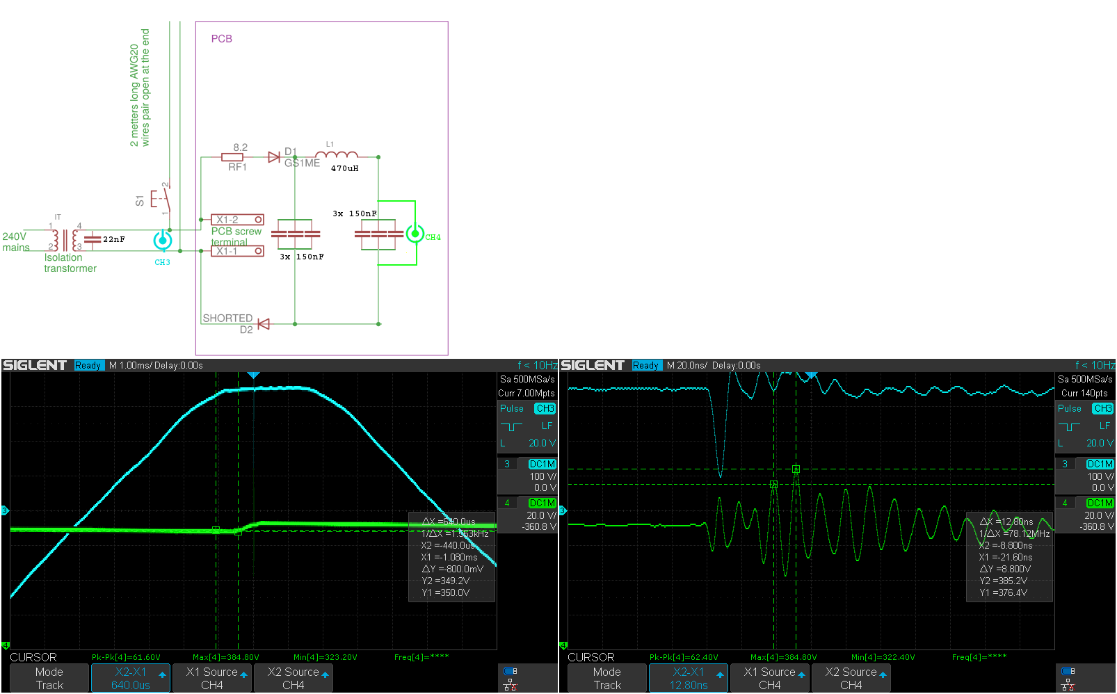
I've then decided to measure the input stage of the circuit in the isolation. So I've de-soldered LNK3205 from the PCB and measured the input caps. See IS22nF_RCLC.png attachment. Clearly there's c.a. 70MHz ringing there but I'm not sure if this is the source of my problem or not... I've also built another PCB with just the input filter but with 3x 150nF ceramic SMD caps (MLCC) instead of each 4.7uF aluminium cap and a bit smaller inductor. That gave very similar results (see IS22nF_RCLC3x150nF.png).
Any further clues what could be the problem here?
Regards,
Witek
| Attachment | Size |
|---|---|
| IS_RDR-506.png | 193.99 KB |
| IS_RDR-506snubber.png | 213.37 KB |
| IS.png | 65.87 KB |
| MAINS.png | 90.24 KB |
| IS22nF-direct.png | 62.61 KB |
| IS22nF_RCLC.png | 109.63 KB |
| IS22nF_RCLC3x150nF.png | 88.91 KB |
Hi Witek,
Why do you need to use transformer in your input? Can't you go directly with the AC input line?
Regards,
Jedidiah
Hi Jedidah,
My target design is powerred dirrectly from AC and I’ve observed the problem when powering directly too.
I use the Isolation Transformer when experimenting/measuring for two reasons
1. Safety - my circuit is isolated from mains.
2. I don’t need to use differential probes (which I don’t have). Otherwise scope’s GND would be connected to mains neutral what causes RCD to trigger in my workshop.
I’ll post a printout from the scope when measuring output in diff mode (two channels ) and with direct supply from mains next week as I’m in the business trip until Saturday. I did measure it in the past and I’ve seen the same problem though.
Hi wsowa,
It seems the problem here is inherent in your AC input line. Do you have other bench that you can measure the AC input line and have a clean sinewave waveform? Is your equipment and bench have proper grounding to prevent any noise captured in the environment?
Regards,
Jedidiah
FYI, I found out that the original MCU reset I've observed was due to other reason. The noise I've picked up on the scope was likely radiated from the board. Thanks your your assistance. All good now.
Hello Jedidiah,
Hello wsowa,
sorry to write here, but I have the problem Jedidiah described here.
Due to the small place on PCB, I had to make a tight layout design, didn't respect the datasheet/AN. I use LNK3205, 1mH inductor, ES1J free wheel diode. Due to the PCB design, I got a 43.3 MHz radiated noise which is over acceptable limit. I tried to play a little with some capacitors in parallel with the diode and the best results I had with a 100-150pF cap. No R in series. I still get over 250mA out in continuous mode. With higher cap value, I got current limitation. But still some noise, still ringing. The ring occurs on the shutdown of the LNK included mosfet.
Any suggestion is welcome.
Later edit: I figured today to build a snubber, consisting of 150pF/630v in series with a 330ohm resistor, placed in parallel with the free wheeling diode, close to the LNK3205.
It is working fine, I understand it is a compromise, but the ringing is much less now, preserving the switching shape.
Greater capacitor values will result in current limitation and LNK working hot.
Thank you,
BR,
Ioan Chiselita
Hi wsowa,
Is your R7 a 100ohms resistor? Can you try to change it to inductor? Also, can you send me a picture of your layout? Please also send measurement across C9 capacitor and Vds (Voltage drain to source) and voltage across D6.
Regards,
Jedidiah