
TOP261YN_HX Family - Current limit
Hi, I have a problem with setting the current limit. In my circuit requirement, there are two current loads, one is the start-up Peak current due to motor inductive load and the other is the Continuous current.
The output Continuous current load takes 100W(24V/4.2A) and I set the current limit resistor (12Kohm) to IC X-pin for around 110W. This protects the transformer from flux saturation.
The start-up Peak current takes around 8A.
Everything is fine under No-load operation the output shows 24V and it can start up and run in continuous current up to 110W (24V/4.6A)
Here comes the problem, the actual Peak current is around 8A. So when the load starts up, the IC instantaneously gets into protection mode due to the setting of the current limit resistor (12Kohm). And there is no output voltage until I reset the circuit by turning OFF and ON the main power.
Is there any way that I can overcome this issue?
It is a full-range (85V~264V) Flyback converter.
Thanks in advance!
![]()
Comments
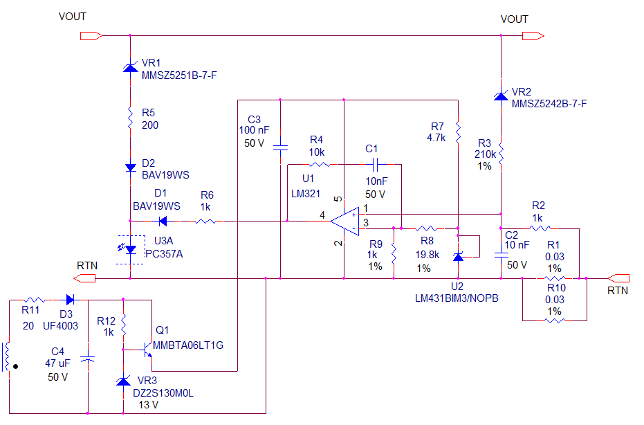
Attached is a circuit that will provide a quasi-constant power characteristic for your power supply. The output current limit will increase as the output voltage falls, until the output reaches ~12V, when the output will transition to constant current mode. The biasing circuit shown should be duplicated on both the primary and secondary sides of the supply (2 separate bias windings) so that the primary and secondary control circuit do not run out of bias as the output voltage falls.
| Attachment | Size |
|---|---|
| Quasi_CP_SCH.png | 32.44 KB |
The are two possible ways around the problem - one is redesign the power supply so that it can deliver the peak startup current without going into protection mode. The other solution would be to to add control circuitry to the output to give the power supply a constant current or quasi- constant power characteristic. The motor would likely spin up slower as a consequence of the output current limitation, but the supply would not go into protection mode.