
Slow Start With Flickering in LNK409 IC
When we start the driver it tooks 10 seconds to reach at 350mA.
it starts with 98mA, gradually increase with some flicker and then set to 350mA.
This doesn't happen if we start it soon after switching it off.
If driver is off for 1 or more hours than this problem arise again.
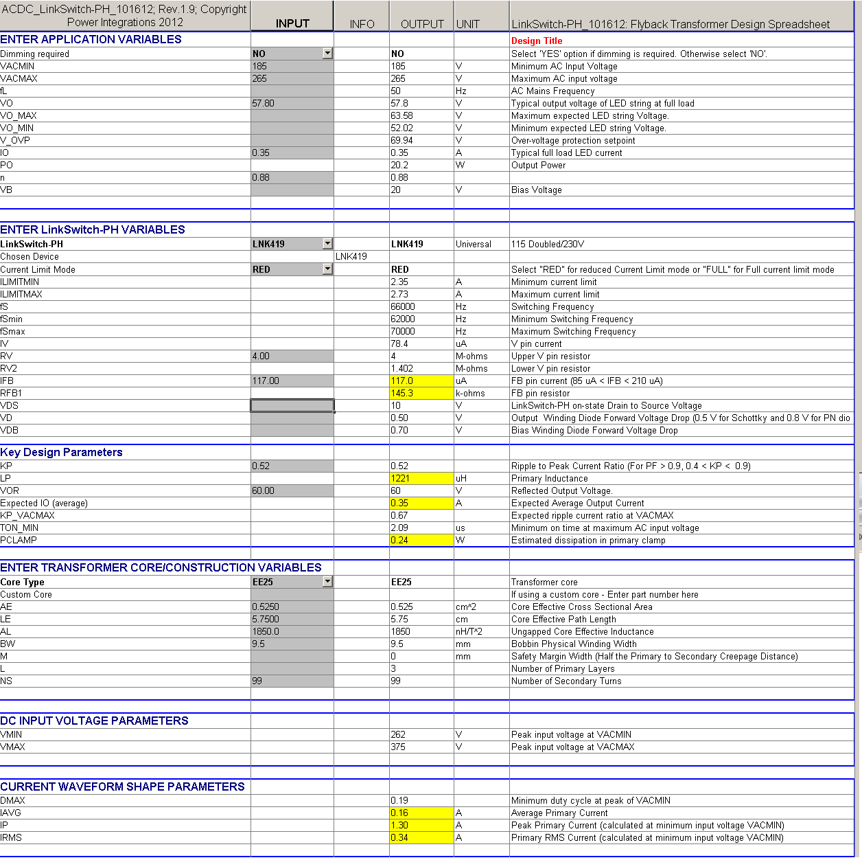
I have attached Circuit and Screenshot of PIXI designer data.
Circuit Data:
Input: 23.12 Watt, 220 V, 50hZ
PF : 0.956
Output: 0.352 Amp, 57.8 Volt
Efficiency: more than 87%
I have made 3 circuits but all have same problem.
I found same problem in another circuit (With Dimmer and Bias Winding)
I have made following changes to Solve my issue but failure.
1) Changes the Main IC LNK409EG
2) Changes Diode BYC8X-600 to DSR6V600
3) Uses Various output Capacitor : 100uF 100V, 220uF 100V, 47uF 100V
4) Changes Feedback Diode 1N4148 to UF4007
5) Discharges Each and Every Capacitor (Input, Output, Bias, Feedback) and Inductor
6) Changes Capacitor in Voltage Pin : 4.7uF 400V to 2.2uF 400V
7) Changes Transformer EE25 to EE30
8) Changes Capacitor parallel to FMMT(82K & 33K) : 1uF to 100nF
9) Checks temperature of each part, Try to cool every part with FAN
10) Checks in Three Stats: Open Frame, Box, Potting, Open frame with FAN
11) Checks with Bias Winding & Input 100E Resister (Series with 2.2mH Filter)
12) Uses 1.5M resister Between Ground & Voltage pin fir tight voltage Control.
13) Removed 100nF Feedback Capacitor
I do not know but I found one weird behavior in circuit : I removed R7 -168k Feedback Resister and still this circuit outputs 115mA Current with 7W.
Everything working good with good efficiency and power factor in this circuit. We Tested it continuously more than 72 hour. There is no problem if we running it continuously without switch it off.
Files
| Attachment | Size |
|---|---|
| 30-Copy Two.png | 86.6 KB |
| 30 - Copy.png | 87.72 KB |
Comments
Thanks for your answer.
I know that it is buck boost converter. But We have followed DER-285. According to DER-285 we have to use spreadsheet for the flyback converter in PIXI.
You can check the DER-285
http://www.powerint.com/sites/default/files/PDFFiles/der285.pdf
It's not only one schematic that uses Flyback convter in PIXI but there are more schematic uses that. like DER-287, DER-356 , DER-298
I have found that DER-341 uses spreadsheet for the Buck converter in PIXIs but it's flyback converter schematic.
The feedback current might be too low.
The calculated feedback current is 95mA at 58 Vout.
It might be necessary to reduce the R7 from 168K to 110K ohms.
As you said, I try to increase the feedback current. But its increase output watts.
So I have made 70V 420mA 30Watt with low R7(Feedback Register) and with higher feedback current (> 130uA).
But same problem as 20Watt circuit.
Excluding this issue my circuit runs very perfact with good stability. I tried to replace many components including IC, transformer and diodes.Tried to change the design of PCBs but failed. Also tried to Increase circuit stability with bias winding but failed.
Let me clear your some doubts with detailed information.
This issue not occuring every time when I switch it on. It's very strange but I had tested 13-15 time to conform that.
1) After making PCB when I switch it on at first time there is no issue. But Issue started after first 8 hours of switch on time.
2) After switching it off for more than 8 hours when I switch it on there is no issue.
3) This issue occures between 1-8 hours of switch off time.
The issue with your board might not be resolved in the Forums.
I think it is better for you to contact your local PI office for technical support to resolve the issue.
I had contacted local PI via email. But No reponse from them.
Anyway I had solved problem in following way.
1) Non Original FMMT560 - Bought new & Original FMMT560
2) BP capacitor & 24.9K Resister put near the IC
3) Put Some Distance between two 2M resisters
Now I am getting 89% Efficiency with 0.975+ Power Factor in 30W Driver
Hi,
It is sad to know that you were not able to get the response from the field. By the way congratualtions you are able to figure out the problem. It came out to be the transistor on the feedback and layout problem.
Regards,
PI-Jono
The attached schematic is buck converter, and the attached PIXL is the spreadsheet for the flyback converter application.
Please use the buck converter PIXL for the buck converter application to have the correct inductance and turns for the output inductor.