
Reducing common mode noise
Hi. My design requires that the output of a high voltage DC-DC converter is low noise (within 20 mV pk pk up to 20 MHz). My TOP255HX based supply provides the DC input for the DC-DC converter. The DC-DC noise is well suppressed with filtering, but the switching noise from the PI based circuit is appearing on the output (50 mV pk pk). Total power is around 12 W. Input 115VAC 60 Hz. When I place a low value capacitor (20 pF) between the D and S of the transformer, it is reduced some. Can you provide some general info of some other things to try further reduce this noise? I am curious about shielding or other circuit techniques. Note that chassis ground is isolated from the output return. Schematic and transformer info and layout attached. thanks!
Files
| Attachment | Size |
|---|---|
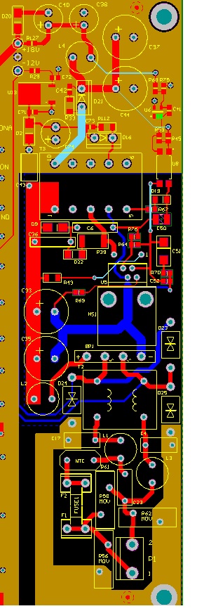
| Layout.jpg | 129.77 KB |
| 18_V_out.jpg | 120.03 KB |
| POL-HX046_TOP255EN.pdf | 147.18 KB |
Comments
I just looked at your layout, and it appears that you are using a ground plane on the secondary side of your supply. A better approach would be to segment the ground plane to ensure that high peak current in the path between your secondary output, your output rectifier, and your first filter capacitor/s flows only in a short loop - otherwise, you can get a gradual distribution of high frequency current that unfortunately includes your output terminals.
You can try adding shields between primary and secondary of your TOPswitch transformer, connecting them to the return of the bulk supply. If you are using a split primary transformer to reduce leakage, you will need a shield for each primary 1/2.
As far as transformer construction is concerned, make sure that the primary winding lead connected to the TOPswitch drain is the start , so that you get the self-shielding effect of the less active primary layers.
Adding a grounded "belly band" around the outside of your transformer may also help, connecting that band to the bulk supply return.
Another possibility would be to add a common mode choke between the output of the TOPswittch supply to the DC-DC converter.
I just looked at your included files, and noticed that you're using a pre-made XFMR. Adding shields would be a problem, but you can still try a grounded belly band using self-adhesive copper tape. The transformer appears to be constructed with the primary start in the right place.
Finally, make sure that you are measuring the ripple properly. A standard scope probe with ground lead forms a huge pickup loop and can give a false impression of actual output ripple. As a quick expedient, you can remove the ground lead and end cap from your probe and use a short length of bare copper wire wound around the ground barrel of your probe in order to do a measurement with the minimum of extraneous pickup.