
Low power design for Energy Metering - using SMD components
Hi
First time on this forum:) The switching products of PI are really awesome!
For my current project, I am following the design guide EPR-89 using LinkSwitch-XT LNK362P to incorporate into my various energy metering products.
I want to convert most of the components (if not all) to SMD, so as to reduce size/weight. Of course a few components like Fusing resistor and switching transformers can still be regular through hole type mount. Has anyone worked in this type of conversion? any experience or hints will be very much appreciated.
Thanks
SilasV
Comments
Hi PI-Kobe
Thank you so much!
I have attached the schematic with this. All resistor are SMD 1206 package except fuse resistor, capacitors are SMD electrolytic, other active components are given as manufacturer part no, which are all SMD type. In this schematic only the EE16 switching transformer and fuse resistor R22 are through-hole type.
I have not yet completed the layout, will soon do that, but will follow general guidelines.
Thanks again!
SilasV
| Attachment | Size |
|---|---|
| LinkSwithModule.jpg | 99.91 KB |
Hi
Further when I looked for the T1 switching transformer (EE16 type) suppliers online, I could not find anyone. I believe this will use PC40 core and I think we will need to wind this in-house Please let me know if there are any suppliers / manufacturers for this transformer.
Is there possibility to replace this with transformer with powdered core type? Since using the powdered core type switching transformer will help make it more temperproof against strong magnets.
Thanks again for your help!
SilasV
Hi
Through reading this forum, I came to know about PIExpert software which I downloaded and ran some sample designs. I think PIExpert is really so awesome!! And I saw that it is possible to have multiple isolated outputs using LinkSwitch-XT switch.
So now I am trying to produce a design which can give me 2 isolated outputs, which was my actual requirement. With only one isolated output of 6V, I would need to use a low power DC-DC converter module. But now with two isolated outputs I would not need that. That would be a great advantage in terms of reducing component count as well as cost.
Thanks
SilasV
Hi
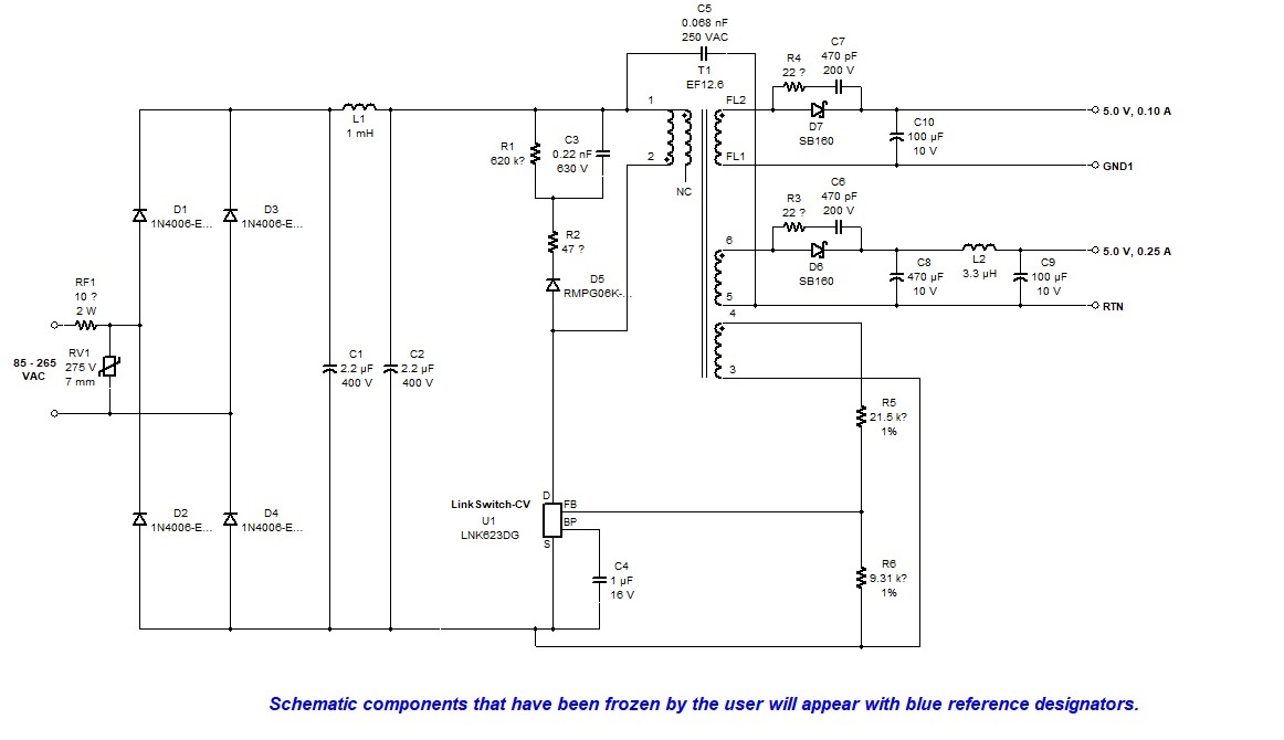
Using the PIExpert, I derived this schematic with two isolated outputs.
I have attached the schematic and BOM with this for your review and comments. I would like to use SMD components wherever possible. Would you please help...
Thanks
SilasV
Hi,
From the schematic, you can examine certain components and recommendations. Generally, for power section components, you may still have to use through-hole parts and for the control section circuitry, you may use SMD components.
You may use through-hole components for the fuse, bulk capacitors, transformers, ferrite beads and output capacitors. As for the rest, you may use SMD components. Efficiency, conducted EMI, board size and layout will be your design constraints in determining which is which.
It is also important to always note the ratings of the devices in choosing the components regardless if it's SMD or through-hole. Hope this helps.
Regards,
Hi Kobe,
Thank you so much for your feedback.
I will work on the layout soon Will get back soon..
Thanks
SilasV
Hi Kobe,
I think instead of making a hybrid combination of SMD and through-hole type components, I would keep it to through-hole type only.
Further, What is the advantage of using carbon film type resistors? is there any way I can replace carbon film resistors with metal film type? Won't the carbon film type resistor be more likely to go up in flame? Although we can choose to use a higher wattage type for given application.
Thanks
SilasV
Hi Kobe
So I am following your guidelines - on the power side I will use the through-hole parts and on the low power side I will use the SMD parts. I also have linear regulators - LP2985 to get 3.3V.
Thanks
SilasV
HI Kobe
I have a question about the transformer design: there are two secondary windings, one of which is marked as FL1 and FL2, - do these leads really have to be flying leads? Can we not use regular pin leads? so a bobbin with 8 leads (4 on each side) can be used. Further can we have the feedback winding connection pins on the same side as primary? this can make the isolation gap on copper side much easy. Will you please let me know your thoughts?
Thanks
Can you send me the transformer build diagram first before I comment?
Regards,
I have attached the diagram
Thanks
| Attachment | Size |
|---|---|
| PSU_Ver2_TX.jpg | 30.74 KB |
Hi,
Just to be clear, you've opted using the LinkSwitch-CV instead of the LinkSwitch-XT right?
Regards,
Oh no:( I realize that error, I actually wanted to use LinkSwitch-XT in open frame, I just ran the PI Expert again and found that the TX design is simply the numbers 1 to 8.
So that should be ok
Thank you so much!
Yes,
I noticed because the feedback winding is usually used for PSR(primary-side regulated) controllers but the originally part that you wanted to use was a LinkSwitch-XT which is an SSR (secondary-side regulated) controller. You may opt to use the newest version of the product, LinkSwitch-XT2.
Regards,
Hi
While working on the PCB layout design, I am so much tempted to use SMD components as much as possible, even on the high power switching side, since the SMD components minimizes the assembly time.
I would also like to provide "filled zones" to maximize the heat dissipation on the high power side. Also the PCB is double sided which will help heat dissipation. My concern is : what is the lowest clearance that can be used on high power side so as not to cause malfunction / sparking considering some humid conditions? The filled zone would be connected to the Source of LNK363G which is basically 0V after rectifier.
Thanks
Hi,
I'm not an expert on safety requirements (clearance and creepage) for PCB but I believe you may search the internet for the appropriate clearance and creepage requirements for the desired application.
You may use SMD components as much as you want however, you should always consider the ratings of the devices. However, for the power section of your design, you may still need to use through-hole components.
Regards,
Hi Kobe
Thanks for your reply
I have another question about the TIW - tripple insulated wire.
Can we use the regular single coated wire in place of TIW? it seems the availability is an issue sometimes, that too for small production. I guess one the main purposes of using TIW would be to avoid insulation break-down at higher temperature / heat generated from continuous 24/7 use. Can we use one gauge size up to reduce mainly the copper losses and reduce heat?
One more thought for PI-Expert application software: Is there any possibility that we can run another design iteration using different winding wire gauge? That would be really nice! it would give the user some freedom of using gauge wire based on availability. The design can a bit flexible, of course the design would then not be under-rated but always up-rated. And for low power designs, in fact under-rating can also be fine, since the currents drawn are in terms of micro-amps these days.
thanks again for your valued help!
Hi,
As for the use of the single coated wire instead of a TIW, it's not recommended due to isolation/safety issues but you may do so provided you take these into consideration in building your transformer. You may use additional tape or other means of isolation to meet safety requirements however the use of a TIW would still be desired.
As per the PI Expert question, I think that you should create another ticket for that in this forum. I hope this helps.
Regards,
HI Kobe
Thank you so much for your reply.
So with using double coated wire, we can provide double or triple tape isolation barrier between primary and secondary windings so as to compensate for not using TIW. Hope that should work.
Further for PI Expert, digging further into it, I could actually override the wire type parameter under Winding Construction -> Secondaries, and change it from TIW to Magnet, it can be done there, and it only changes the layer thickness to slightly lower value as compared to TIW (which is of course expected). So I guess we will try out a few samples and see how it goes.
Thank you so much again for your valuable information!
Best regards
Hi,
Can you send me the schematic, BOM and layout so I can help you out with this?
Regards,