
Reducing Radiated EMI
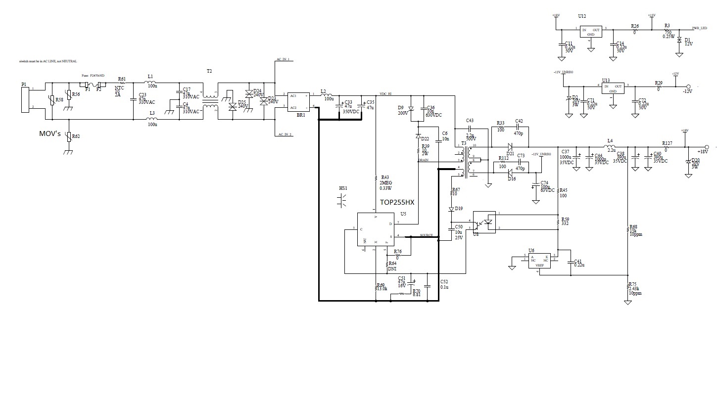
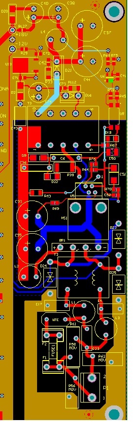
Hi PI staff and forum. I am curious about some more ways to reduce EMI. My AC-DC supply powers another switcher with a DC rail (and a negative bias rail). I noticed that even when the rest of the unit is off, the EMI from the AC-DC is picked up on the other side of the enclosure (the output is separate from the output of the AC-DC supply). When I put in another supply like that of a small laptop brick (which conveniently fits in same spot) I do not see any EMI picked up on the connector of the unit. This is even evident in how much less is picked up by the scope probe 2 inch away. Examining this brick shows several folded layers of shielding tied to the low DC side of the bridge rectifier output. But even removing the shielding the EMI is much much less. And this is a much higher power supply (even though running unloaded). I noticed the transformer is toroidal which in general is better for EMI. Is this a major contributor to keeping the EMI so low? Does PI have a design similar to this brick with info on a toroidal transformer, shielding specific to laptop bricks? If not, what does PI recommend for a low EMI solution in terms of a controller, etc? My design, layout attached.
Files
| Attachment | Size |
|---|---|
| 18_V_out.jpg | 117.01 KB |
| Layout.jpg | 124.04 KB |
| physcial_layout.jpg | 48.06 KB |
| Transformer (from Premier Magnetics) | 147.18 KB |
Comments
Thanks you PI-Wrench - sounds like good advice! I will be pursuing and following up.
I looked at the data you provided, and the first thing that rang alarm bells is the use of a ground plane in the secondary layout. This allows the HF return current from main output capacitors C37 and C44 to spread out and infect both the output and other portions of the board. This can cause issues for both HF output ripple and EMI. The return from capacitors C37 and C44 should be a short, direct trace from the capacitor negative terminals to the transformer return. This also goes for the return from capacitor C74.
Using proper layout it is possible to get acceptable radiated EMI performance using a single-sided PCB.
Capacitors C37 and C44 should be located closer to the secondary side of T3 for a more direct return path. I'm not certain of your output power, but it may be possible to use one filter capacitor instead of two for your +18V output, making layout more compact. You can also use 25V rated capacitors rather than 35V capacitors and still have commercially acceptable voltage derating. The lower voltage capacitors will be smaller and help to make the layout more compact. UCC KZE or Panasonic FM series caps are readily available and are good candidates for your application, being compact capacitors with low ESR and high ripple current rating.
Running a trace from your TOPSwitch heat sink directly to the return of C33 will also help to reduce radiated EMI. The TOPSwitch uses an integrated lateral mosfet that results in a quieter heat sink tab, but grounding the heat sink to primary return will reduce radiated EMI even more.